Vibratory finishing equipment is used to deburr, polish, descale, clean and radius manufactured parts in bulk. Instead of removing burrs by hand, the process places parts inside a vibrating chamber with abrasive media, water and finishing compound. The machine transfers controlled motion into the media mass, producing thousands of abrasive contact events across each batch.
For metal parts manufacturers, this process is often the most economical way to convert rough machined, stamped, cast, forged or additively manufactured parts into assembly-ready components. It is widely used in aerospace, automotive, medical device, hydraulics, electronics, hardware and precision machining operations because it improves edge safety, surface consistency and downstream coating performance while reducing manual labor.
The right vibratory finishing system is not selected by chamber size alone. A profitable process depends on part geometry, burr condition, material hardness, required surface roughness, edge radius target, batch volume, media selection, compound chemistry, water flow, separation method and automation level. A bowl vibratory finisher may be the best choice for general CNC deburring. A tub finisher may be required for long aerospace components. A centrifugal disc machine may be justified when short cycle time is the priority. Drag finishing may be the correct solution for high-value medical implants or precision turbine parts where part-on-part contact is unacceptable.
This guide explains how vibratory finishing equipment works, how to compare major machine types, how to select abrasive media, how to control process variables and how to evaluate ROI before purchasing a finishing system.
1. Introduction: What Is Vibratory Finishing?
Vibratory finishing is a mass finishing process in which parts and media move together inside a vibrating work chamber. The media acts like a flexible abrasive tool. It reaches external surfaces, edges, holes and accessible recesses, removing burrs and smoothing surface peaks through repeated rubbing, rolling and sliding contact.
Common objectives include:
- Deburring drilled, milled, turned, stamped, laser cut and cast parts
- Polishing or pre-polishing before plating, anodizing, passivation or coating
- Edge rounding to improve handling safety and reduce stress concentration
- Descaling heat-treated, forged, cast or welded components
- Cleaning oil, light oxide, loose fines and machining residue
- Creating a more uniform cosmetic or functional surface finish
Compared with manual deburring, vibratory finishing offers higher batch throughput and better repeatability. It also reduces ergonomic risk and supports more predictable quality control. Compared with blasting or belt grinding, vibratory finishing is gentler on complex geometries and can process many small parts at once.
The process does have limits. Deep blind holes, severe rollover burrs, very tight dimensional tolerances and mirror-finish requirements may require special media, staged processing, masking, fixturing or a secondary finishing operation. The goal is to develop a controlled process window, not simply run parts longer until they look acceptable.
2. Working Principle
Vibratory finishing equipment works through three linked mechanisms: vibration motion, media and compound interaction, and controlled material removal.
Vibration Motion
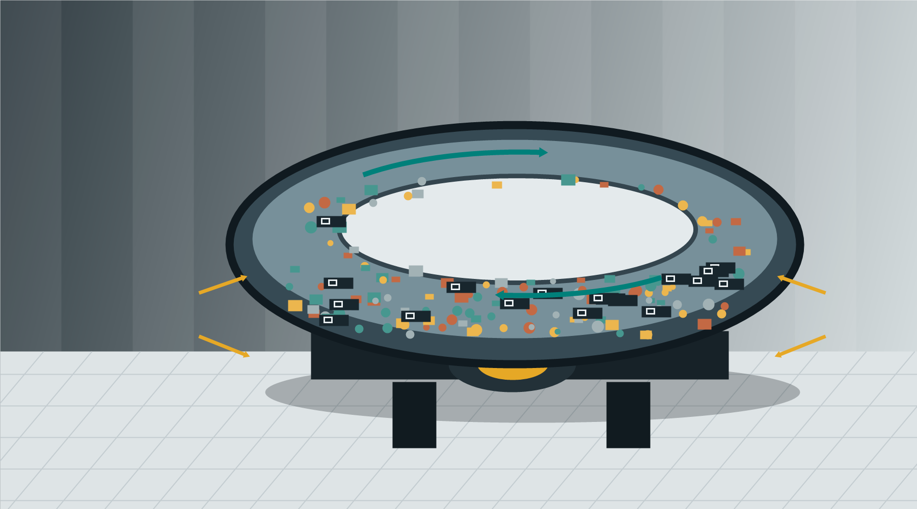
Most vibratory finishers use an eccentric weight system or unbalanced motor. As the motor rotates, the eccentric mass generates centrifugal force. That force moves the bowl, tub or chamber through a repeating vibration pattern. The media and parts respond by rolling, sliding and circulating.
In a bowl vibratory finisher, the load normally moves in a toroidal roll around the annular channel. In a tub finisher, the load moves as a rolling wave through a trough-shaped chamber. In centrifugal disc finishing, a rotating disc accelerates parts and media at higher energy. In drag finishing, parts are fixtured and pulled through a media bed at controlled speed and orientation.
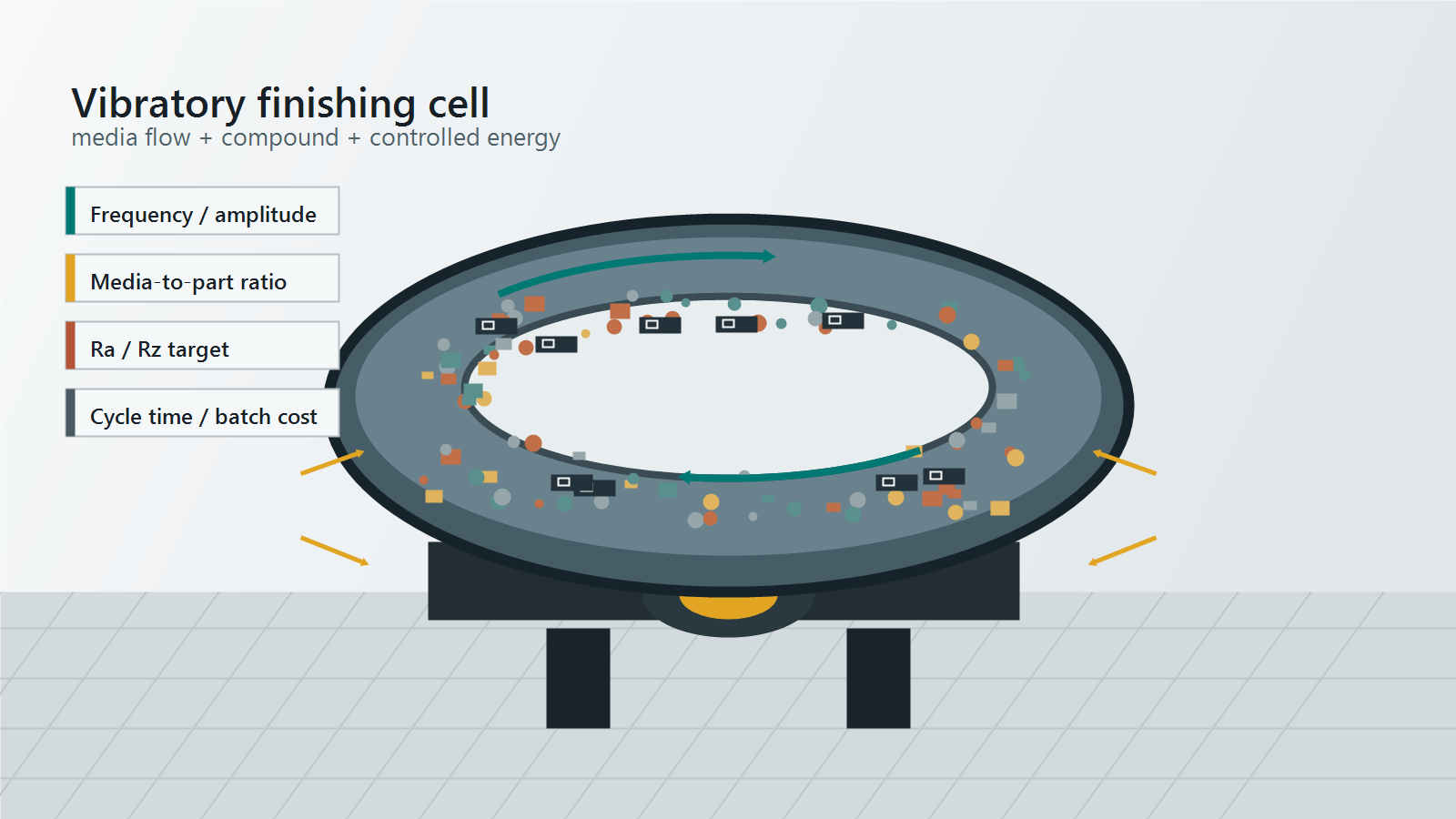
Important energy variables include:
- Frequency, expressed in Hz or cycles per minute
- Amplitude, or chamber displacement per vibration cycle
- Eccentric weight setting
- Chamber geometry and lining hardness
- Total media and part load weight
- Media-to-part volume ratio
Process intensity is approximately related to frequency and amplitude:
Relative finishing energy approximately proportional to Amplitude x Frequency^2This is why a small frequency increase can noticeably increase cutting action. Higher energy can shorten cycle time, but it can also cause part damage, media lodging, excessive edge rounding or rapid media wear. A good process uses enough energy to meet the specification without over-processing the part.
Media and Compound Interaction
The finishing media provides mechanical action. The compound solution controls chemistry. Water transports compound, removes fines, limits temperature rise and helps carry debris out of the chamber.
Compounds are not basic soaps. Depending on the application, they may contain surfactants, builders, corrosion inhibitors, lubricants, brighteners, pH buffers and chelating agents. For aluminum, zinc and magnesium, chemistry must prevent staining and chemical attack. For stainless steel, titanium and medical alloys, chemistry may focus on cleanliness, residue control and compatibility with passivation or validation requirements.
Material Removal Mechanism
Material removal is selective because burrs and roughness peaks protrude into the media path. These high points receive more contact pressure and are removed faster than flat surfaces. Removal occurs through abrasive cutting, cyclic burr fatigue, micro-fracture, sliding wear and, in burnishing processes, surface compression.
A basic material removal rate formula is:
MRR = (W_initial - W_final) / (A_exposed x t)Where MRR is material removal rate, W_initial and W_final are part weight before and after finishing, A_exposed is exposed surface area, and t is cycle time.
For production control, measure burr height, edge radius, weight loss and surface roughness. If Ra or Rz is part of the specification, define the measurement direction, cutoff length, instrument type and sampling plan. See Surface Roughness Measurement for a deeper guide to Ra, Rz and inspection consistency.
3. Types of Vibratory Finishing Equipment
Bowl Vibratory Finishers
Bowl vibratory finishers are the most common choice for general deburring, radiusing, polishing and cleaning. The annular bowl creates continuous media flow and can often include an internal separation screen so finished parts unload while media returns to the process chamber.
Best-fit applications include CNC machined parts, fasteners, fittings, small die castings, stamped parts, fineblanked components and general hardware. Bowl systems are compact, versatile and cost-effective. They are also relatively easy to integrate with conveyors, separators, dryers and compound dosing systems.
The main limitations are part size and part fragility. Long, flat or delicate parts may overlap, nest or damage each other. Media shape must also be selected carefully to avoid lodging in holes, threads or slots.
Tub Vibratory Finishers
Tub vibratory finishers use a rectangular or trough-shaped chamber. They are preferred for long, large, heavy or delicate components that do not circulate well in a bowl. Divider plates can reduce part-on-part contact, and open access makes inspection and manual handling easier.
Typical applications include aerospace brackets, shafts, extrusions, machined plates, investment castings, medical instruments and components requiring gentle rolling action. Tub machines are highly flexible, but separation is often less automated than with bowl systems unless external screens, magnetic separators or custom discharge systems are added.
Centrifugal Disc Finishers
Centrifugal disc finishers are high-energy machines. A rotating disc at the bottom of the chamber accelerates the media and parts, generating intense relative motion. They can achieve much shorter cycle times than conventional vibratory bowls, especially for small parts with heavy burrs.
They are often used for stamped components, small machined parts, dental parts, jewelry, medical components and high-volume precision parts. The tradeoff is aggressiveness. Thin edges, soft alloys and cosmetic parts may require lower speed, cushioning media or reduced loading to prevent damage.
Drag Finishing Machines
Drag finishing machines hold parts in fixtures and move them through a media bed. Since parts do not tumble freely against each other, drag finishing is ideal for high-value parts where impact damage or uncontrolled orientation is unacceptable.
Common applications include orthopedic implants, turbine blades, aerospace components, precision gears, cutting tools and additive manufactured metal parts. Drag finishing generally has higher equipment and fixture cost, but it offers excellent repeatability, controlled edge rounding and strong process validation potential.
4. Key Technical Parameters
When comparing vibratory finishing equipment, request more than total chamber volume. A 300 L machine from one supplier may perform very differently from another if motor power, spring design, lining thickness, separation system and control package differ.
| Parameter | Why It Matters | Buying Consideration |
|---|---|---|
| Capacity, L | Indicates chamber volume | Confirm usable working volume, not just total size |
| Batch weight, kg | Defines load limit | Include media, parts, water and fixtures |
| Motor power, kW | Drives process energy | Match power to heavy loads and media density |
| Frequency | Controls contact rate | Variable frequency improves process tuning |
| Amplitude | Controls media roll intensity | Adjustable eccentric weights add flexibility |
| Cycle time | Determines throughput | Validate with sample parts |
| Media load ratio | Controls cushioning and access | Common ratios range from 3:1 to 10:1 by volume |
| Lining material | Protects machine and parts | Polyurethane hardness affects wear and impact |
| Separation method | Determines labor requirement | Internal separation improves production flow |
| Compound control | Stabilizes chemistry | Dosing pumps improve repeatability |
Usable part capacity can be estimated as:
Usable part volume = Chamber volume x Fill factor / Media-to-part ratioFor a 300 L bowl, 70 percent fill and 5:1 media-to-part ratio:
Usable part volume = 300 x 0.70 / 5 = 42 LThis estimate must be checked against part weight, part geometry and separation requirements. Dense steel parts may reach the weight limit before reaching volume capacity. Large flat parts may require reduced loading to prevent nesting.
5. Performance Metrics
Performance should be specified with measurable acceptance criteria. Visual inspection alone is not enough for aerospace, automotive or medical production.
| Metric | Measurement Method | Why It Matters |
|---|---|---|
| Ra | Profilometer or optical measurement | Average surface roughness |
| Rz | Profilometer peak-to-valley value | Peak reduction and coating behavior |
| Burr height | Microscope or optical comparator | Confirms deburring effectiveness |
| Edge radius | Microscope, radius gauge or 3D scan | Controls edge rounding |
| Weight loss | Precision scale | Tracks total material removal |
| Cycle time | Production timer | Defines throughput |
| Reject rate | Quality records | Measures process capability |
| Media wear | Weight or volume loss | Controls consumable cost |
Ra is widely used, but Rz is often more informative when peak height affects sealing, coating, fatigue or tactile feel. Edge radius should be measured when parts require controlled rounding rather than simple burr removal.
Consistency depends on stable media level, load size, compound concentration, water flow, cycle time and machine energy. A process that passes every time in 70 minutes is often more valuable than one that sometimes passes in 40 minutes and sometimes fails inspection.
6. Abrasive Media Selection
Media selection determines cutting speed, finish quality, lodging risk, part protection and operating cost. Equipment and media should be evaluated together during application testing.
Ceramic Media
Ceramic media is dense, durable and available in multiple abrasive grades. It cuts efficiently and is commonly selected for steel, stainless steel, cast iron, titanium and hard alloys.
Advantages include high cutting rate, long life, strong edge rounding and broad shape availability. Limitations include higher aggressiveness on soft metals, potential part impact damage and lodging risk if shape and size are poorly matched.
Ceramic media is usually the first choice for robust steel or stainless parts with defined burr removal requirements.
Plastic Media
Plastic media is lighter and gentler than ceramic. It is often used for aluminum, zinc die castings, brass, copper and softer alloys where surface appearance matters.
Advantages include reduced part damage, good pre-plate or pre-anodize smoothing and controlled cutting on soft materials. Limitations include faster wear, lower cutting rate on hard metals and higher organic sludge load in wastewater.
Plastic media is a strong option for cosmetic aluminum, zinc die castings and parts that need smoothing without aggressive edge attack.
Steel Media
Steel media is used mainly for burnishing, brightening and surface compaction. It is not normally selected for heavy burr removal. Its high density creates strong rubbing and compression, producing bright surfaces on suitable materials.
Advantages include long media life, bright finishes and low abrasive breakdown. Limitations include corrosion risk, high machine load and limited cutting ability. Steel media requires proper compound chemistry to prevent rust and maintain brightness.
Shape and Size Selection
| Media Shape | Strength | Lodging Risk | Common Use |
|---|---|---|---|
| Triangle | Good edge access | Medium | General deburring |
| Cone | Good access to radii and holes | Medium to high | Complex machined parts |
| Cylinder | Strong linear contact | Medium | Edge break and smoothing |
| Angle-cut cylinder | Good flow and access | Medium | General finishing |
| Ball | Low cutting, high burnish | Low | Brightening and polishing |
| Pyramid | Aggressive point contact | High | Heavy burr removal |
Media should be small enough to reach the required surfaces but large enough to avoid lodging. Review all holes, counterbores, slots, threads and undercuts. A practical rule is to ensure at least one media dimension is larger than any feature where lodging is unacceptable, unless the process is designed for media to pass through.
For ongoing consumable control, connect media choice with Media Life Cycle Analysis and Abrasive Quality Control.
7. Process Variables
Time
Longer time increases material removal, but it also increases media wear, machine utilization, energy use and risk of dimensional change. If cycle time becomes excessive, review media grade, media size, amplitude, frequency or machine type instead of simply extending the run.
Media Condition
Media wears during production. New media may cut sharply, while worn media becomes smaller and more rounded. As media shrinks, lodging risk can increase. Production systems should include media level checks, wear tracking and replacement rules.
Media cost per batch = Media wear kg per batch x Media price per kgCompound Chemistry
Compound concentration affects cleaning, corrosion protection, foam, brightness and residue. Low concentration can cause staining or dirty parts. Excess concentration increases cost, foam and wastewater load.
Compound use per batch = Water flow rate x Compound concentration x Cycle timeAutomated dosing is recommended for multi-shift production because it reduces operator variation.
Water Flow
Water removes fines, carries compound and controls temperature. Low flow causes sludge buildup and dull finishes. Excessive flow can wash away compound, reduce lubricity and increase wastewater cost. Closed-loop systems may require settling, filtration, centrifuges or chemical treatment.
8. Applications
Deburring
Deburring removes sharp or loose material from machining, drilling, milling, stamping, laser cutting and casting. Vibratory finishing is most effective when burrs are thin enough to abrade or fatigue away. Heavy rollover burrs may require upstream tooling changes or pre-deburring.
Polishing
Vibratory polishing smooths surfaces and improves brightness. It can be used before plating, anodizing or passivation. Mirror finishes may require staged processing with fine media, porcelain media, steel burnishing media or a secondary polishing step.
Descaling
Descaling removes oxide from heat treatment, forging, casting or welding. Abrasive ceramic media and suitable compounds can remove light to moderate scale. For thick oxide or profile creation, Shot Blasting Machines may be more efficient.
Edge Rounding
Edge rounding improves safety, coating coverage, fatigue behavior and tactile quality. Conventional vibratory finishing can create general edge breaks. Drag finishing or tightly controlled high-energy processes are preferred when a specific edge radius must be documented.
9. Comparison of Equipment Types
| Equipment Type | Speed | Cost | Precision | Automation Level | Best Fit |
|---|---|---|---|---|---|
| Bowl vibratory finisher | Medium | Low to medium | Medium | High | General deburring and polishing |
| Tub vibratory finisher | Medium | Medium | Medium | Medium | Large, long or delicate parts |
| Centrifugal disc finisher | High | Medium to high | Medium to high | Medium to high | Small parts and short cycle time |
| Drag finishing machine | High | High | High | Medium | High-value precision parts |
Choose a bowl finisher for general-purpose production when parts can tumble freely and automated separation is important. Choose a tub finisher when parts are large, long, fragile or unsuitable for circular bowl flow. Choose a centrifugal disc finisher when cycle time must be short and parts are small enough for high-energy processing. Choose drag finishing when part value, edge precision or damage prevention justifies fixturing and higher capital cost.
10. ROI and Cost Analysis
A vibratory finishing purchase should be evaluated by total cost per accepted part, not equipment price alone. Important cost drivers include machine investment, initial media charge, media wear, compound use, labor, utilities, wastewater, maintenance, floor space, rework and scrap.
| Cost Item | What to Include |
|---|---|
| Equipment cost | Machine, controls, lining, separation, automation and installation |
| Media cost | Initial fill plus ongoing wear |
| Compound cost | Cleaner, brightener, rust inhibitor or special chemistry |
| Labor cost | Loading, unloading, inspection and maintenance |
| Utilities | Power, water and compressed air if required |
| Waste handling | Sludge, wastewater and spent media |
| Quality cost | Rework, scrap, returns and inspection failures |
Cost per batch can be estimated as:
Cost per batch =
(Labor minutes x Labor rate per minute)
+ (Machine hourly rate x Cycle hours)
+ Media wear cost
+ Compound cost
+ Water and waste cost
+ Quality loss allowance
Cost per part is:
Cost per part = Cost per batch / Accepted parts per batchAccepted parts per batch is more important than loaded parts per batch because rework and scrap change the real economics.
Example: a shop manually deburrs 600 parts per shift at 45 seconds per part.
600 x 45 sec = 27,000 sec = 450 min = 7.5 labor hoursIf a vibratory finisher processes the same volume in three batches with 20 minutes of operator handling per batch:
3 x 20 min = 60 min = 1 labor hourLabor reduction is 6.5 hours per shift. At USD 35/hour and 250 shifts per year:
Annual labor savings = 6.5 x 35 x 250 = USD 56,875Payback period is:
Payback period = Total installed investment / Annual net savingsAnnual net savings should subtract media, compound, maintenance, utilities and waste treatment. For high-volume automotive or machining operations, direct labor reduction may dominate ROI. For aerospace and medical applications, scrap reduction, validated repeatability and lower rework can be the stronger economic justification.
11. Buying Guide and Internal Links
Before requesting a quote, prepare real production data. A supplier cannot accurately size vibratory finishing equipment from material and part name alone.
Provide:
- Part material, hardness and heat treatment condition
- Part drawings or 3D files with critical features marked
- Current burr height, burr location and burr direction
- Target Ra, Rz, edge radius or visual standard
- Batch quantity, hourly throughput and annual volume
- Part weight and maximum part envelope
- Holes, slots, threads or features where media lodging is unacceptable
- Downstream processes such as plating, anodizing, passivation or coating
- Cleanliness, corrosion, validation or documentation requirements
Ask the supplier for:
- Sample processing report with before-and-after photos
- Recommended machine type and chamber capacity
- Recommended media type, shape, size and grade
- Compound chemistry and concentration
- Cycle time and expected throughput
- Media wear estimate and consumable cost
- Separation method and residual media carryout risk
- Utility requirements, maintenance schedule and lining life
- Spare parts, service support and commissioning plan
A strong supplier will evaluate the complete finishing cell: feeder, vibratory finishing machine, compound dosing, water management, separation, rinse, drying, inspection and consumables. The machine is only one part of the production process.
For related technical resources, link this page to:
- Surface Roughness Measurement
- Media Life Cycle Analysis
- Abrasive Quality Control
- Shot Blasting Machines
Commercial CTA
If you are evaluating vibratory finishing equipment for deburring, polishing, descaling or edge rounding, start with an application trial using your real production parts. Share your drawing, material, burr condition, target finish, required throughput and downstream process requirements. A process engineer can recommend the right bowl finisher, tub finisher, centrifugal disc finisher or drag finishing system, together with the correct ceramic, plastic or steel media and compound chemistry.
Request a process review for:
- New vibratory finishing equipment
- Media and compound selection
- Cycle time reduction
- Surface roughness and edge radius improvement
- Cost-per-batch analysis
- Replacement of manual deburring
- Automation, separation, drying and wastewater planning
A properly selected vibratory finishing system can reduce labor, improve consistency, lower rework and create a repeatable path from rough manufactured parts to finished components ready for assembly, coating or inspection.